Lost foam casting is a technologically advanced process that is gaining popularity in the casting industry. It is known for precision in forming, minimum machining allowance, and production cleanliness compared to traditional processes like clay sand casting and resin sand casting. Lost foam casting is also less polluting, has lower energy usage, low-cost production, and lower technical demands on workers.
However, the lost-foam casting process is relatively new in some markets, and there are some technical challenges to be addressed. Some firms have been using the technology for several years, but they haven’t yet come close to the exact size they want in their castings. If things get bad enough, there won’t be enough material left to machine.
This blog post describes the reasons behind the geometrical accuracy of castings in the foam casting process focusing on manual fabrication of foam patterns. It provides solutions and may serve as a reference while producing foam patterns in lost foam casting process.
Understanding the Lost Foam Casting Process
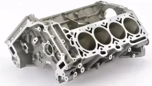
In the lost foam casting process, a pattern made of polystyrene foam is coated with a refractory material (a coating resistant to high temperatures), placed in sand, and then molten metal is poured directly onto the foam pattern. The heat of the metal vaporizes the foam, leaving a casting that replicates the shape of the original foam pattern.
Key Factors Affecting Dimensional Accuracy
Several factors can influence the precision of the final casting, beginning with pattern creation and extending through pouring and cooling. Paying close attention to each stage is essential for achieving the desired accuracy.
Pattern Design and Fabrication
The initial steps in the lost foam casting process are crucial for accuracy.
White Mold Template Technology
- White Mold Design: Base the white mold design on mechanical part drawings, incorporating machining allowances and casting requirements. A casting drawing can be created either from the mechanical part drawing or independently.
- Process Drawing: Develop a process drawing that breaks down the white mold into separate foam pieces or modules. Fewer modules result in fewer glued surfaces, enhancing white mold precision and reducing gas generation during pouring due to less adhesive.
- Template Drawings: Create template drawings that specify the part name, drawing number, material, scale, and sequence number. Indicate the direction if necessary. Arrange the sequence starting with the larger pieces. It’s important to avoid using one template as a sample to make others, as this can cause the accumulation of error.
- Scaling: Determine the appropriate scaling ratio based on the casting material and structure. For example, when casting iron, decide whether to use a shrinkage ratio of 0.8% or 1.0%.
- Template Material: Choose cardboard of appropriate weight. Monitor cardboard templates for thermal wear and replace them as needed, or use galvanized iron sheets for large production runs.
- Positioning Circles: For circular parts, use common outer or inner diameters as positioning circles for the separate pieces. Use the same drawing tools to lay out these circles on cardboard or galvanized sheets, and have one person do the cutting to prevent errors.
- Cutting Gaps: Account for the width of the cutting gaps produced by the hot wire when cutting the foam. This width varies with the hot wire’s diameter and temperature, and should be measured and adjusted for in production.
- Adhesive Subtraction: Dimensional increases occur after gluing due to the flatness accuracy of the white mold pieces, the thickness of the glue, and warpage after gluing. The more mating surfaces there are, the greater the increase in casting dimension. This increase is the adhesive subtraction value. Reduce this value in advance when cutting. The amount of adhesive subtraction depends on the specific situation and can be detected in the first white mold. A lack of consideration for adhesive subtraction is a major cause of insufficient machining allowance.
Material Selection
Use foam with a suitable weight per unit volume that cuts smoothly, is strong, resists deformation, and produces minimal gas after thermal melting.
Cutting Process
- Calibration: Ensure the hot wire is parallel to the cutting bed to maintain consistent thickness in the foam layers, which is essential for geometrical accuracy.
- Initial Cutting: When cutting the original foam block, carefully select the first cutting surface to serve as a reference for all subsequent cuts.
- Template Fixing: Secure the templates to the upper and lower surfaces of the foam, ensuring accurate alignment using reference surfaces. Use appropriately sized nails to fix the template in place, ensuring the nail is perpendicular to the template.
Assembly and Bonding
Positioning
Align foam modules using common dimensions such as inner holes or outer perimeters. Accurately transfer the location of internal features like ribs by tracing them from the template onto the foam. A more direct method involves creating openings on the template to act as guides for positioning the ribs.
Bonding
Control glue thickness and concentration, as these affect the adhesive subtraction value. Apply glue sparingly, focusing on sufficient adhesion while minimizing gas generation and drying time.
Bonding Sequence
For white molds with multiple bonding surfaces, establish a logical bonding sequence. Apply weight as needed to prevent warpage, ensuring even pressure to avoid deformation.
Bonding Time
Allow adequate bonding time based on room temperature. Ensure each bonded surface is secure before proceeding to the next to prevent gaps from forming.
Sealing
Seal the edges of the bonded surfaces to prevent coating penetration and create necessary casting fillets using paper strips, rounded edges, or wax.
White Mold Finishing
After bonding, grind casting fillets, fix any defects, and conduct a final inspection of dimensions and shapes.
Pouring System Design
Develop a suitable casting pouring system based on technical requirements, casting structure, and production process. Use bottom-pouring or stepped pouring systems instead of top-pouring whenever possible. Place the ingates on machined surfaces to facilitate handling, coating, and sand filling.
Coating Application
Apply the coating in multiple layers, typically three coats, allowing each coat to dry thoroughly before applying the next. The first coat should be highly refractory with fine particles, while subsequent coats should focus on strength and air permeability with progressively larger particles.
Pouring
The pouring process in lost foam casting differs significantly from traditional casting. Molten metal in lost foam casting experiences rapid cooling due to the negative pressure. A slower pouring rate increases the temperature difference, which can affect casting shrinkage and geometry. While increasing the filling speed can reduce the temperature difference, it must be balanced with adequate time for foam melting to prevent back or collapse.
Cooling and Shakeout
Allow sufficient cooling time before shakeout to prevent issues like cold cracking, deformation, and difficulty in machining. The cooling time depends on the casting material and weight.
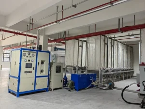
Equipment Provided by Hangzhou Ouchen Technology Co., LTD
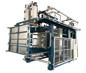
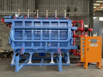
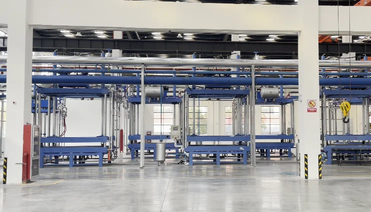
Hangzhou Ouchen Technology Co., LTD distinguishes itself through the production of high-end, intelligent lost foam equipment, presenting an array of solutions including EPC Pre-Foaming Machine, EPC Sheet Machine, EPC Cutting Machine, Lift Type Paint Mixer, and EPC Air Dryer. By integrating Hangzhou Ouchen Technology Co., LTD’s machinery, organizations can amplify productivity, diminish energy consumption, and uphold elevated benchmarks of quality.
- Pre-Foaming Machines:The fully automatic pre-foaming machine ensures stable barrel temperatures using electromagnetic heating, preventing “dead beads” and allowing for versatile material pre-release.
- Foam Sheet Machines:The foam sheet machine adjusts plate size with encoder control, offers automated operation, and uses a sequence of negative pressure and pulse high flow cold air for cooling.
- Lift Type Paint Mixer:The paint mixer consists of a main mixing disperser and a mobile mixing anti-sedimentation immersion coating tank.
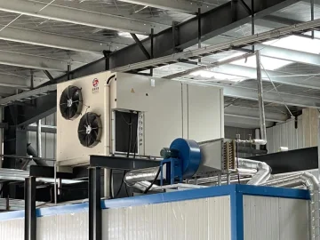
- Air Dryers:Air dryers, such as top-mounted, rear-mounted, and indoor models, effectively eliminate moisture from foam patterns and coatings, thereby mitigating defects in the final castings. The indoor air dryer, for example, consolidates heat pump technology, condensation methods, and heat recuperation strategies for efficient and eco-friendly drying.
Conclusion: Achieving Precision in Lost Foam Casting
Elevating the precision of your lost foam casting process calls for a comprehensive strategy, spotlighting pattern engineering, material assortment, coating deployment, and process oversight. Embracing state-of-the-art apparatus from dependable lost foam casting manufacturers can further sharpen your competencies, culminating in superior castings and heightened productivity. By tackling these pivotal facets, you can unlock the complete spectrum of advantages of lost foam casting, realizing phenomenal precision in your castings.